
The Destemmer/Crusher
I was planning to make the move to making wine from grapes and knew I needed to get a good crusher destemmer. I had found a couple here and there ranging from $300 used to about $1000 new. Then, I noticed a post on winepress.us that showed a homebuilt destemmer/crusher. The order of the processes is different, where the grapes are destemmed first, then crushed. They do not make an affordable hobby sized version of this machine and I was not going to spend $2500. I looked at the machine someone else built and thought I could build one too.
The first obstacle I had was that I didn’t have a lot of power transmission experience. By that, I mean the pulleys and such. So, I knew I had some learning to do. Luckily, an article in winemaker magazine had detailed how to build a crusher/destemmer, so a lot of the same principles apply. I decided to design the destemmer portion first.
Destemmer
For the destemmer, it is essentially a set of “fingers” arranged in a helical fashion that push the stems and grapes out towards the end. The fingers rotate within a basket that has holes that are big enough for the grapes, but not for the stems. That way, the stems get pushed out the end, while the grapes fall through to get further processed. The first step in this was to design the box. So, I knew that it would essentially be a compartment for dropping the grapes in and a section to house the destemmer. Based on what I had seen, the section of for the grapes in could be small, about 14” long x 12” wide. The space for the destemming had to be a lot longer to ensure that it got all the grapes off of the stems. So, that was 36”. This meant I had to make a box 48” long and 12” wide. To do this, I ripped and cut 4 pieces of ¾” plywood. I then screwed these together to form the basic box. The front and two sides were solid, but the end I had to cut a 12” diameter hole in the center so that the stems could be pushed out and the destemming basket would fit. I simply drew the 12” diameter circle and cut it out with a jigsaw. I then had to make the grape compartment separate from the rest by placing a piece of 3/8” HDPE and cutting a 12” diameter hole directly in the center. This is where the grapes would be pushed from the compartment where they were placed into the destemming portion. This was placed 12” from the front of the box. Now, in order for the grapes to be pushed into the destemmer portion, I had to make an auger to push them along. This meant that the floor of the grape compartment had to be curved to allow all the grapes to be pushed through. In order to do this, I cut 2 semicircles of ¾” plywood and placed them in the bottom of the grape compartment. This allowed me to push down a piece of 1/8” HDPE into those semi circles to create the curve that the auger would fit into (but I didn’t place that in yet). Now, I had my basic box, but I needed a top to contain the grapes in the destemming portion. I wanted to make a removable top, so I cut a piece of ¾” plywood 1 ½” wider than the box and as long as the destemming portion. This allowed for a ¾” overlap on each side. I then cut a piece of 1/8” HDPE sheet to go over this on the destemmer side. On the ¾” overlap, I screwed in pieces of ¾” stock. On this stock, I was going to place latches in order to hold down the top, but also to make it removable. So, I fastened the catch of 4 latches to the ¾” stock. This completed the frame of the box.
The next step was to make the basket for the destemming portion. Knowing that I had a 12” Diameter, using the equation c=πd, this meant that the material had to be approx. 37 inches wide. Since I need some overlap to fasten it together, I opted to make it 39”. Then came the tedious process of drilling the holes. The holes are ¾”, so they are spaced 1” apart. I drew a grid on the 1” intervals and the just started drilling with a step drill. After about an hour of straight drilling, I was done. Now, I had to fit it into the box that I built and then secure it together. Once it was in the box and conformed to the holes I built, I drilled 8 new holes in the overlap portion to fit ¼” x 20 stainless steel bolts. These have the stud face upward, so the protrusion into the destemming section is only the rounded head. I then had to secure the basket to the box. In order to do this, I cut a piece of stainless steel and then bent it into an L shape. I then drilled a hole through the back plate of the box and through the basket, then made corresponding holes in the bracket. This effectively holds the basket in place.
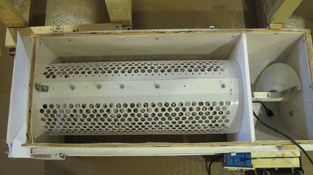
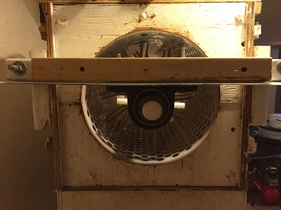
Now that all of the static pieces were built, it was on to the shaft. The shaft required two sections, one for the auger and one for the destemming, but first I needed to get the shaft to turn in the box. The front was easy. I simply drilled a 1 ½” diameter hole and placed a mounted bearing against the outside of the box and bolted it in. The mounted bearings had a set screw, so I had no worries about it being secured. On the back side, I had to make a cross bracket to hold the pillow block bearing in place. I did this by having 2 2x4 blocks on the outside of my box, and then cutting another 2x4 to go across. I then secured this by drilling two holes (one on each side) through the blocks and then putting long bolts through. This allows me to remove the cross arm and do any cleaning. I then mounted the pillow block bearing on the cross arm (with two bolts drilled up through the cross arm). The biggest problem was that the shaft is actually larger than 1 ½” in diameter. So, when you buy a HDPE rod, the size is greater than what it says. I had to sand down each end of the shaft in order for it to fit. I did this by hand and it was a tremendous chore. A lathe would have worked much better to get it down to the correct size.
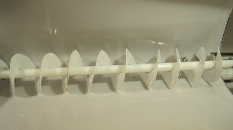
I now had to make the fingers for the shaft. In order to do this, I marked for each finger to be 1 ½” in distance from one another, and ¾” of a turn. Once I made all of the marks, I used a milling machine to drill the holes. These holes are slightly larger than ½” (taking into account the larger diameter than what they are sold as). I then cut pieces of ½” HDPE rod at 6” and then inserted them in those holes. I then used some semi flexible silicone tubing, ½” inside diameter to fit over those rods.
The next part was to build an auger in the front portion of the top part into which I could drop the grapes. The auger would then push the grapes into the destemming portion. For this, I utilized the ideas behind Archimedes screw. I simply took a sheet of 1/8” HDPE sheet and cut it in an oval roughly 14” in diameter. I then cut a 1 ½” hole in the center using a hole saw and then a single cut from the outside to the inside. I then slipped it over the rod and stretched it out. This indicated where I need to cut it. The inside hole had to be cut somewhat and the outside had to be trimmed. I tried using the calculation, but it was easier to cut a little, try again, and cut some more. I then made two stainless steel brackets to hold the auger in place. These are bent at a 60 degree angle to accommodate the helical nature of the auger. I then drilled two holes through the rod to attach the brackets and two holes through each end of the auger. I put stainless bolts through these and tightened them. When spinning the auger, there was no rubbing and it pushed things along just fine. This completed the portion of the top part that was needed. However, I wasn’t going to crank this thing by hand.
The next step was to attach the motor. I bought a new ¼ HP, 1725 RPM reversible motor. I then placed a 3” pulley on it and then put a 12” pulley on the rod with the fingers. I then simply took a V-belt and attached the two. Getting the exact size required buying a couple different belts and deciding which fit best. I then hooked up the motor to a switch, which is powered by a GFCI receptacle (since we’ll be dealing with liquids, I didn’t want to have any problem). This completed the top portion of the machine. It was now onto the tray into which the grapes would fall after being destemmed.
The tray
For the tray, I needed to essentially build a section for the grapes to fall into and then an auger to pull the grapes towards the crusher. In order to do this, I built a plywood box, the same size as the top portion. I then made arches to be able to hold the HDPE sheet in a curved fashion. This would allow me to make an auger that ran down the middle to screw the crushed grapes towards the crusher rollers. I put in 3 arches, stopping 15 inches from the end of the box. First, I put a single piece of HDPE sheet on the end, extending all down the box. I then took a single piece of 1/8” HDPE sheet and layed it into arches. I then screwed this into the sides. Next, I put a smaller piece of HDPE sheet on the last arch, so that none of the plywood would be exposed to the grapes.
The next step involved the auger. I essentially utilized the Archimedes screw. I took another piece of 1” HDPE rod and ran it down the center of the curvature created in the arches. The top of the rod is 3 inches above the bottom of the arch. I had to buy two bearings (one for each side) and then I drilled the holes for the rod and the bolts securing the bearings. The key was to line the rod up with the top rod so that the eventual pulley would be directly below the other one. Now, I had to make the auger screw. I did this by making a cardboard cutout in a circular shape with a 1” hole in the middle. I then put it on the rod and stretched it. I then kept trimming it in the center and on the edges until it was pretty close to fitting. There is a formula to calculate the size of the center hole and the outside diameter, but it never worked for me. I then made 7 discs of the same size and then bolted them together with ¼” stainless steel bolts. I then placed it on the rod and stretched it out (like an accordion). I then made two stainless brackets (one for each end) and then attached the auger to the rod. I then spun the rod to see where I had to do any trimming on the auger. Since the cuts weren’t perfect, I had to take some off and sand down some edges. Once I made sure the auger would spin freely, I added a small pulley to the outside of the rod, making sure it would line up with the pulley from the destemmer portion. I also put on a sprocket to eventually power the rollers.
At the end of the box (having left the 15” at the end open) was where the crusher rollers were going to go. However, I now needed to build the frame to keep it off the ground so that I could put on the crusher box. I attached a 2x4 to each side of the bottom box (with the auger) and extended it farther passed the box and into the pulley area. I then used another 2x4 to attach the two boards together on the pulley side. I then built the legs. I knew I wanted to be able to put a brute bucket underneath, so I made it high enough (making sure to take into account the crusher box yet to be built). Also, since I wanted to be able to put the bucket in and out, I left a gap on the bottom. This required a little extra work to make it stable (some additional cross bracing). I then put 6 casters on the bottom to make it movable. This allowed me to move it by myself, but more importantly, allowed me to now work on the crushers.
To build the crusher box at the end of the bottom box (with the 15” open end), I built a small box (dimensions) out of ¾” plywood that had a funnel shape to it. To do this, I cut two pieces (dimensions) for the front and back, and then took one piece on each side and angled it so that the grapes would fall towards the rollers. I then cut another two pieces to go straight down from those angled ones to create the space for the rollers. I then covered all of this plywood with 1/8” HDPE sheet. Now, to create the rollers.
The rollers are tricky. The first thing I did was buy two 2” HDPE rod pieces of 12”. I then had to put grooves in the roller to be able to grab the grapes and get them crushed. I think that leaving it smooth would not be able to pull the grapes to be crushed. To do this, I set up my router bench with a (don’t know the name) and had ½” inch of the bit sticking up. I then ran the rod over it, making an angled groove. I repeated this multiple times on each rod. The next part was to drill a hole down the center of each with a lathe. I did slightly smaller than a ¼” of an inch. It was now time to assemble the crushers within the machine. So, I drilled two holes on each side of the box, leaving enough room for a ½” space between the rollers. I placed small nylon bushings in each hole to manage the wear and tear. I then lined everything up and put a 24” ¼” stainless steel rod down the center. This was slightly tricky as it involved tapping the rod through the box and into the crushers. The crusher holes were tight (on purpose), so I just had to tap quite a bit as I did not want to overexert and bend the stainless rod.
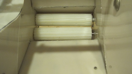
The next part was to make the gears for the crushers. I went to a website and found a free gear template and then printed it out and pasted it onto an old cutting board with a glue stick. At first, I used a jigsaw and the gears came out terribly. For the next try, I used a band saw, it came out much better. I then drilled a slightly less than ¼” hole in the center of each and slipped them onto the outside of the box. I then attached a sprocket to one of the rods. This sprocket was for 40 roller chain. I simply lined up the two sprockets, measured the chain required, and cut to fit. I attached the chain and it was ready to go.
A video with a description of some of the main components: